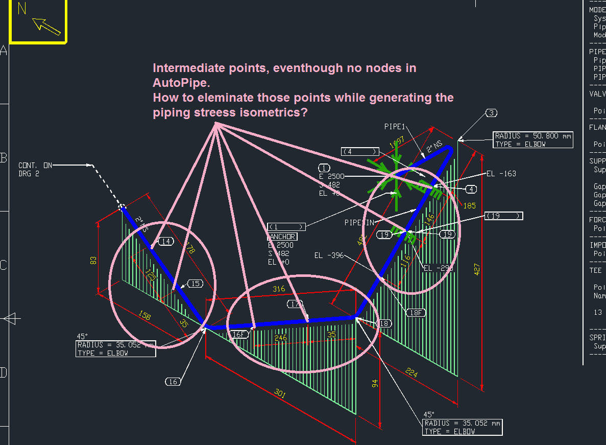


Items and information that are shown on an ISO include the following: The various runs of pipe, fittings, and valves should be roughly in proportion for easy understanding. It gives all information necessary for fabrication and erection of piping. Piping “isometric” and “spool” drawings shows a complete line from one piece of equipment to another. Figure 13.8 illustrates the representation of the north arrow on the arrangement drawing and the north arrow on the isometric. In the piping discipline a north arrow is used as a “point of reference.” Accurate isometric layout is based on the correlation of the orientation of the north arrow on the Piping Arrangement drawing and the north arrow on the piping isometric. The complexity of piping configurations requires a more descriptive “point of reference” be used to establish orientation between the orthographic and isometric views. Although the A can be seen in Figures 13.3 and 13.4, it is not an adequate point of reference. Similarly, on piping isometrics, establishing a point of reference is imperative.

By using a point of reference, proper orientation of the isometric can occur by transferring distance and direction from the orthographic view. Moreover an isometric is not overcrowded with other information, useless for piping and it is easy to visualize.Note in Figures 13.1 and 13.2 how the height, width, and depth dimensions of the L-shaped object in the orthographic views are oriented on the isometric view with A as a point of reference. Isometric drawings are easier to be used for stress analysis of the piping, fabrication and construction, compared to other orthographic drawings, since they carry all the necessary information for these tasks. Upon completion and approval of the piping isometrics, they are used for fabrication and then construction of the piping system. For complex piping systems, individual pipe runs are represented on separate isometric drawings.A table gives the number and detailed description of each type of fittings represented on the drawing.In addition, all the fittings including, valves, flanges, elbows etc.The operating and design process conditions (pressure and temperature) for the pipe run may also be reported on the isometric.This line number is indicative of the fluid service, piping class and material, insulation etc. The line numbers for lines pipe runs represented on the drawing is clearly indicated.Straight lengths of all the pipe runs on the drawing are reported as clearly as possible.


 0 kommentar(er)
